


In this video I’m going to show you how to make an interactive LED coffee table.
This unique LED coffee table can create beautiful atmosphere and will be a real focal point in my living room. I wanted to make a simple design with some interesting features that will take my room to a whole new level.
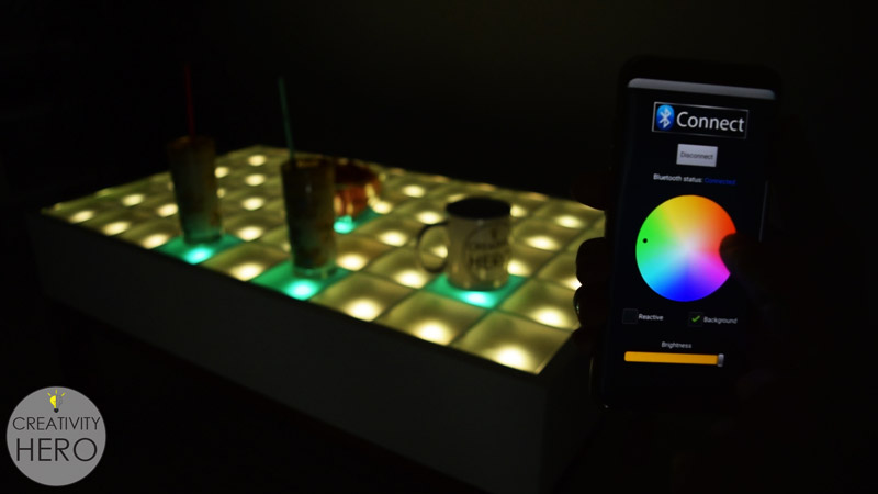
It is controlled via a custom-made Android application, so I can easily change the reactive color, or the background color, and I can even adjust the brightness.
This interactive LED coffee table is made out of MDF for the box, a pine for the legs, a glass top and its inner part consists of an Arduino board, a Bluetooth module, LEDs, proximity sensors and a bunch of wires.
Here’s the video where you can see how I made this interactive LED coffee table step by step.
Here are the materials I used:
- MDF board (your local hardware store)
- Pine board (your local hardware store)
- Glass top (your local hardware store)
- Arduino Mega Board
- Bluetooth Module
- Addressable LED Strip Light WS2812B
- Infrared proximity sensors
- Wood glue
- Wood filler
- Masking tape
- Oil based paint
- Rosewood stain
Types of tools I used:
- Circular saw
- Random orbit sander
- Cordless drill
- 90 degree angle clamps
- Band clamp
- F-clamps
- Paint roller kit
- Pocket hole jig
- Soldering iron
- Multimeter
- Wire strippers
- Glue gun
Disclosure: As an Amazon Associate I earn from qualifying purchases.
Now, let’s start with the build.
Related: DIY Mid-Century Modern Side Table / End Table
Step 1: Cutting the MDF and the Pine to Size.

First, I’m cutting all the pieces to size on my table saw. I’m going to make a box out of MDF. I’m using 18 mm thick MDF for the sides, and 8 mm thick MDF for the bottom.
Most of the pieces I cut using my table saw fence.
Inside the box I’ll create a grid out of MDF, so I need to cut 12 pieces 4 cm wide.
For the legs and the frame below the box, I used a large pine board. It was warped, and I don’t have a plainer which means I needed to make a lot of cuts and adjustments in order to flatten all the pieces.
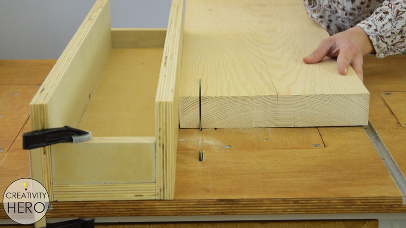
To cut all the pieces to the right length I used the crosscut sled. For making repeated cuts I mounted a stop block. Some of the pieces were much longer, so I set the fence and clamped a scrap of plywood on it, which will actually serve as a stop block for the longer pieces.
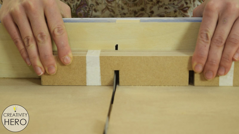
For the grid I should make dadoes onto each MDF piece, so that they can easily lock together and make a perfectly squared grid.
So, I marked all the points for the dadoes, wrapped the pieces together with a masking tape, set my blade on the appropriate height and made all the cuts.
Here’s the 3D model and the plan for this interactive LED coffee table with all the dimensions:

Step 2: Sanding the Pieces.
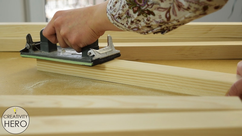
I started with 80 grit sandpaper and then continued with 120 grit, until everything was nice and smooth.
Step 3: Assembling the box.
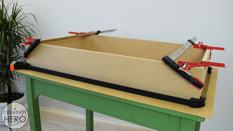
First, I assembled the box. I applied a nice amount of wood glue, and joined the pieces together with corner clamps and a bend clamp.
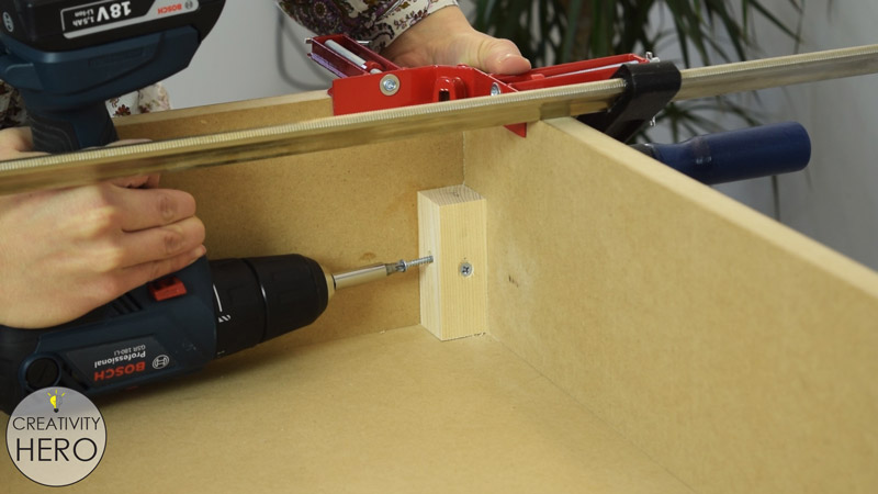
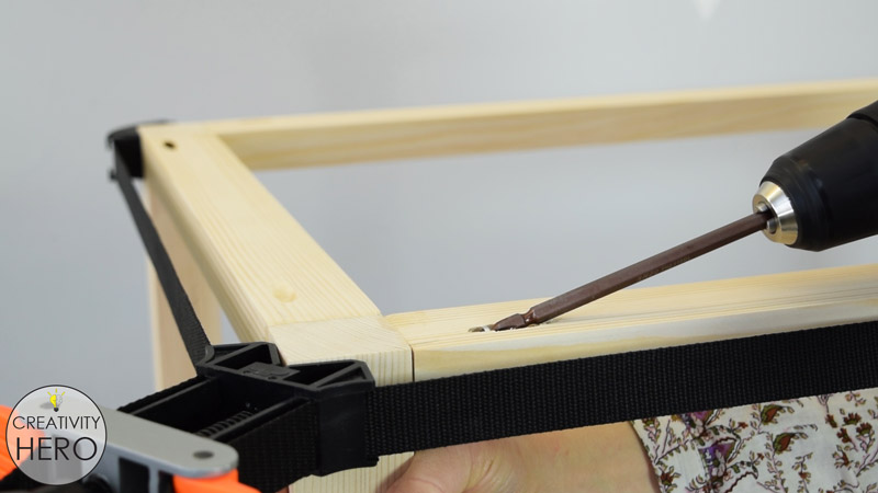
To make stronger connection between the sides of this frame, I added a small piece of wood in each corner and secured them well.
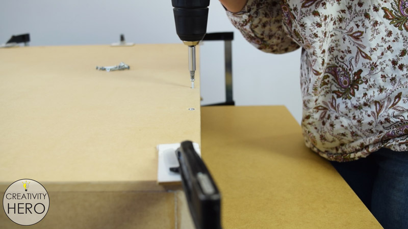
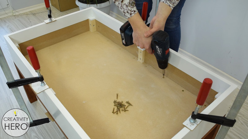
After that I can secure the bottom of the table with a wood glue and a lot of screws . I pre-drilled holes, and then inserted countersunk screws.
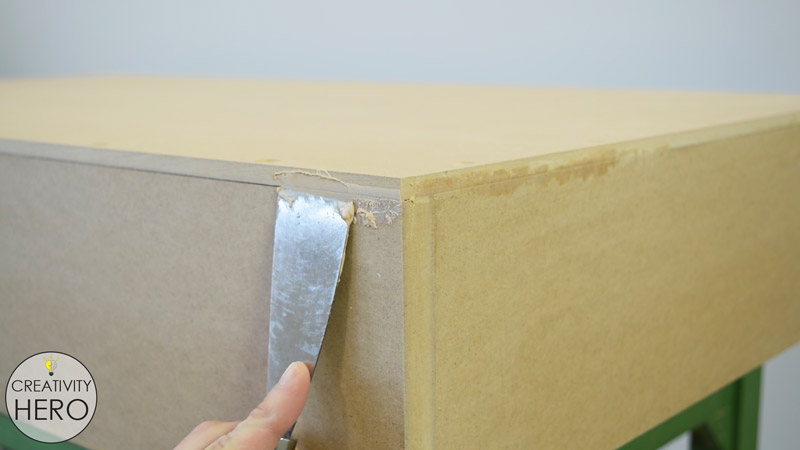
In order to avoid any gaps I’m applying a wood filler on the joining parts of the table.
I made two openings on the bottom of the table, one for the high-voltage cable, and other for the switch. Using a rasp I made the opening for the switch a perfect fit.
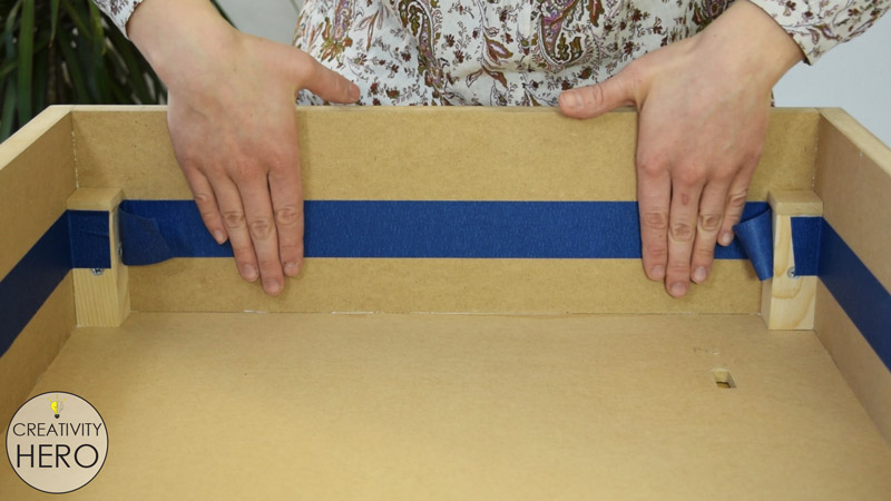
When I placed the smaller MDF board into this box, I noticed that it was warped in the middle due to its length, so I added 2 more small wooden pieces into the box for better support.
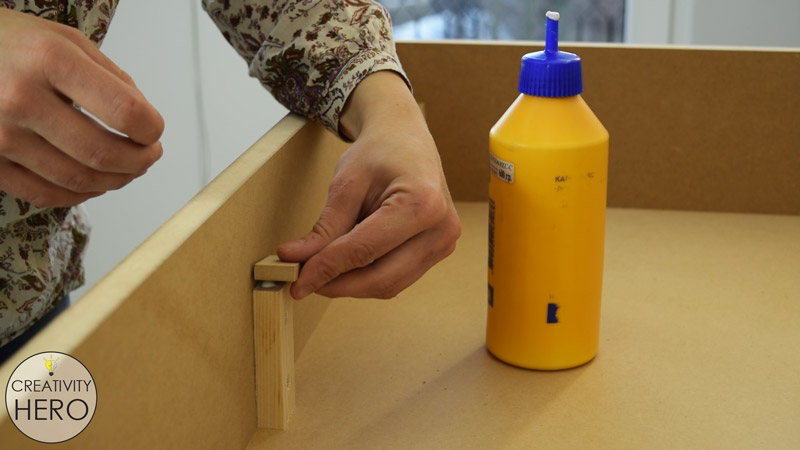
Then, I measured the depth of the box, and also realized that I should add extra 8 mm height onto those small wooden pieces so that when I finally place the glass on the top it would be flush with the sides.
Luckily, I had 8 mm thick MDF which is perfect for this purpose. I cut 6 small pieces of it and glued them on top of the pieces that I previously attached.
I fine sanded the MDF to remove the extra wood filler and prepared it for painting. Then, I wiped the dust off of the surface with a wet rag.
Step 4: Painting the MDF Box.
I don’t have to paint the entire inner part of the table, so I applied a masking tape on the sides to get straight, clean paint lines.
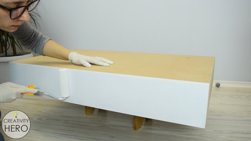
After that, I applied an oil based primer using a roller for large surfaces, and a brush for the areas that are hard to reach.
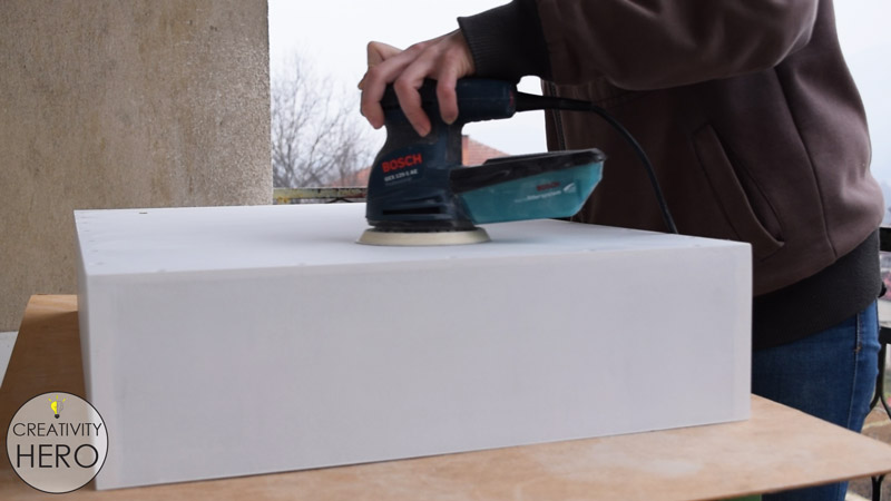
I left it to dry overnight, and sanded the surface with my orbital sander using 120 grit sandpaper.
Now it is time to apply paint. I chose an oil based white paint, and carefully applied it on the surface making sure I cover every part of the table.
All the pieces that will be used for the grid inside the table I painted white as well.
Step 5: Assembling the Legs and the Frame below the Box.
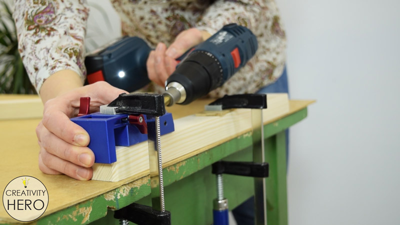
The legs and the frame below the table I’ll join together with pocket hole screws. The pocket hole jig that I have is very useful and easily adjustable tool for making pocket holes.
I wasn’t able to make two pocket holes on each side due to the width of the strips, but later I can mount corner brackets if needed.
Before attaching the screws, I’m applying a wood glue for stronger connection. In order to make the pocket holes invisible, I inserted the screws on the top of the frame.
Again I applied a wood filler into the gaps and left it to dry. Then sanded the excess to prepare it for staining.
Step 6: Staining the Frame and the Legs.
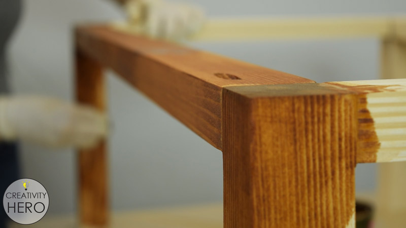
When it comes to the stain, I applied a rosewood stain to get a nice contrast between the top and the legs. I did the same in my previous project, and it turned out wonderful.
Step 7: Assembling the Entire Table.
What’s left to do is to join the two parts of the table together. I clamped the top with the bottom, pre-drilled holes with a countersink drill bit and then used a lot of screws to secure them together.
Related: How To Create A 3D Paper Cut Light Box | DIY Project
Step 8: Preparing the MDF Board for The Electronics Part.
The electronic parts that I’m using are: Addressable LEDs, Infrared proximity sensors, an Arduino Mega board, a Bluetooth module, 5V power supply and a bunch of wires.
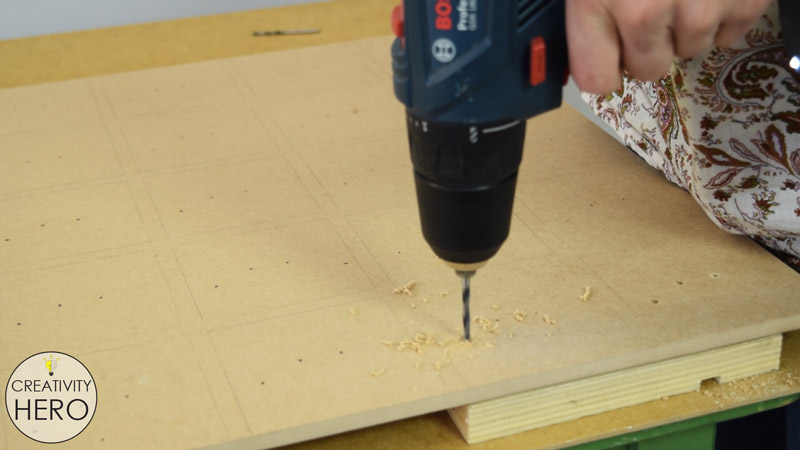
I’ll attach everything onto one MDF board. It will be divided into 45 squares.
So, first I’m using a template to drill 3 holes into each square, and onto each square I’ll insert an LED and a proximity sensor, and connect them with some wires.
Step 9: Preparing the LEDs.
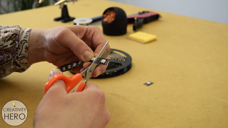
Then, I cut 45 LEDs into individual pieces from this strip.
I need to cut 5 cm long pieces of red and black wire and strip off around 5 mm of the insulation on their ends. I’ll use one pair of those for each LED and another pair for each proximity sensor.
I’m doing the same with a green wire, but here I’m cutting longer pieces and also stripping off their ends.
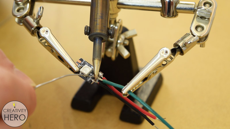
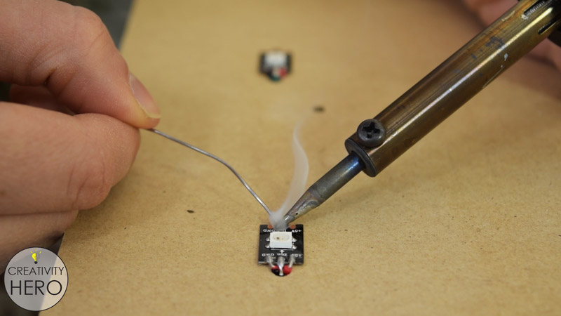
Then, I’m soldering the wires onto the LEDs. The black and the red I’m soldering on the Ground and the 5V pad, and the green one in the middle or on the Data IN pad.
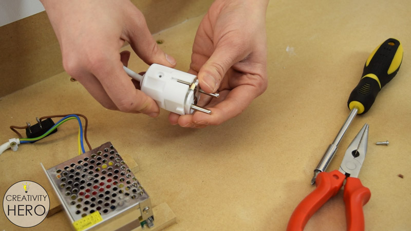
Step 10: Preparing the IR Proximity Sensors.
After that I can move on to the proximity sensors. I separated the IR transmitter and the IR receiver and made a larger distance between them.
In a normal position, the sensor won’t be able to detect a glass on top of the table, because the glass won’t reflect the Infrared light. In this way I can position the transmitter and the receiver at an angle so that the light can be reflected to the receiver on the other side.
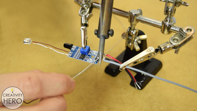
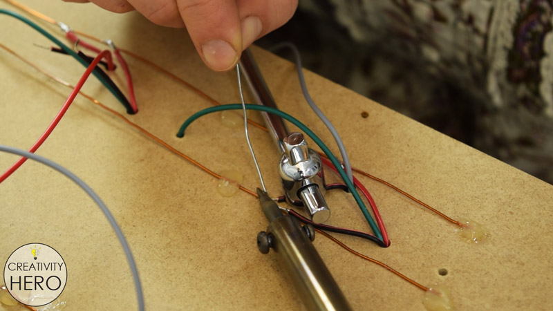
So, I’m removing the transmitter and soldering it back on the sensor, but this time with 4 cm long wires. I used single core wires from an Ethernet cable, because they can be easily bent and stay in that position.
On the other side of the sensor I need to solder the black and the red wire to the Ground and 5V pin, and a longer grey wire to the Output pin that will connect the sensor to the Arduino board.
I need to solder pin headers onto the longer wire ends, so they can be easily inserted into the Arduino board.
To insulate them I’m using a shrink tube and a lighter.
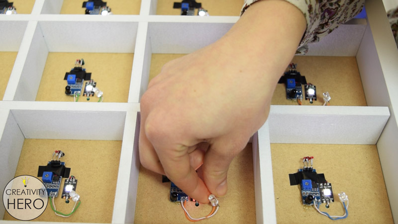
Step 11: Attaching the LEDs and the IR Proximity Sensors onto the MDF Board.
Now, all the LEDs and the sensors are ready to be attached onto the MDF board.
The LEDs are the first to be attached onto the board. I inserted them into the holes that I previously drilled, peeled off the tape cover on the back, and stuck them onto the board.
Then I connected them by soldering the green wire in the middle of each LED, or the Data OUT pad of the previous LED to the Data IN pad of the next LED.

Once I’m done with the LEDs, I’ll do the same with the proximity sensors. This time I’ll hot glue them next to the LEDs. Here I need to pay attention to the length of the grey wires. All of them will be inserted into the Arduino board which will be positioned in the middle of the back side of the board.
So, the cables that are further from the Arduino board are longer, and as they are coming closer to it they become shorter.
The IR transmitter and the receiver need to be placed facing up, so I’m making some adjustments here.
Step 12: Connecting all the Wires and Inserting them Into the Arduino Board.
Now I’ll turn the MDF board to the back and connect all the wires.
I’ll start with hot gluing copper wires along with the length of the board. They will be used as power lines for the LEDs and the proximity sensors. On the first line I’ll solder all red wires, and on the other line all black wires.
Before soldering, I need to remove the insulation off of the copper wires with a sandpaper, otherwise I won’t be able to solder them.
It took me a long time until I finished soldering all the wires. At the end I connected all the positive and all the negative lines.
Also, on these lines I soldered two more wires which I’ll later connect to the power supply.
I added 330 ohms resistor between the first LED and the Arduino, to reduce the noise on that line.
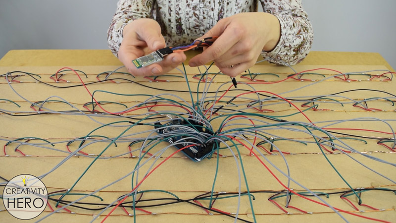
All the wires are ready, so I carefully insert them into the Arduino board in order.
Here I’m also inserting the Bluetooth module.
The Circuit Schematic
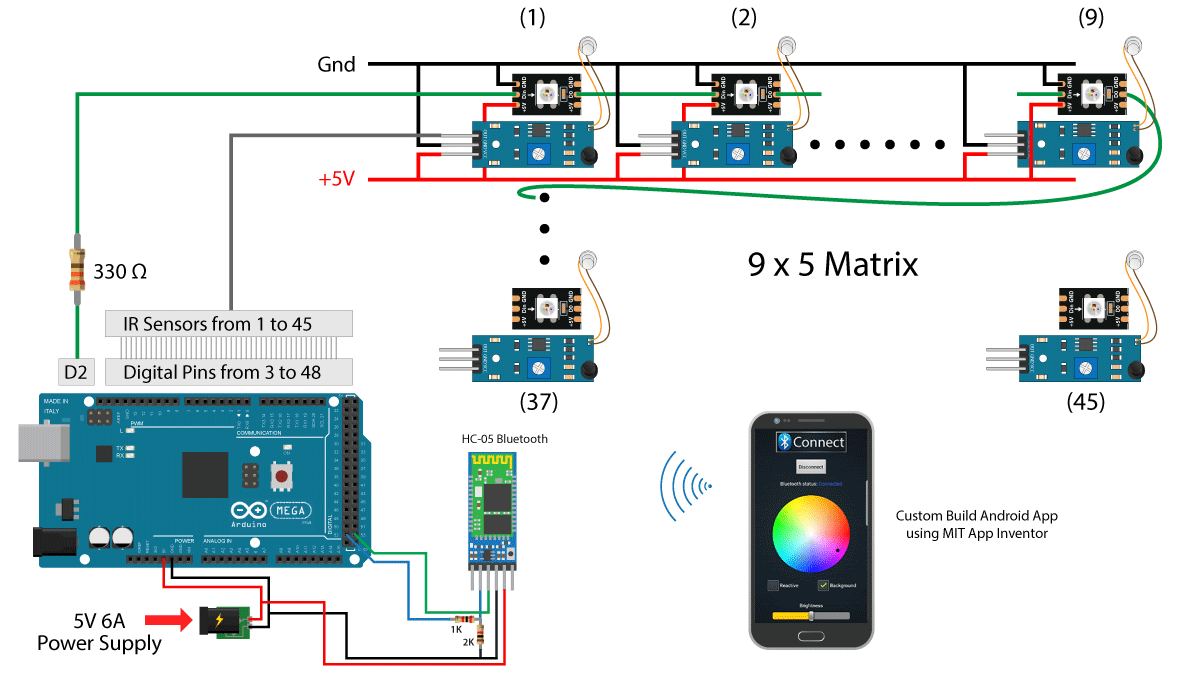
This is the complete circuit schematic where you can see how I connected everything together. For more details on how to use the Arduino in combination with these addressable LEDs and the Bluetooth device you can check Dejan Nedelkovski YouTube Channel, and his website www.howtomechatronics.com.
He made a tutorial on how everything works, including the source code of the program and the custom-built Android application.
Dejan makes awesome videos in the area of Mechatronics and Electronics, as well as cool Arduino projects providing complete explanation, circuit schematics and source codes.
Step 13: Mounting the Power Supply Inside the Table.
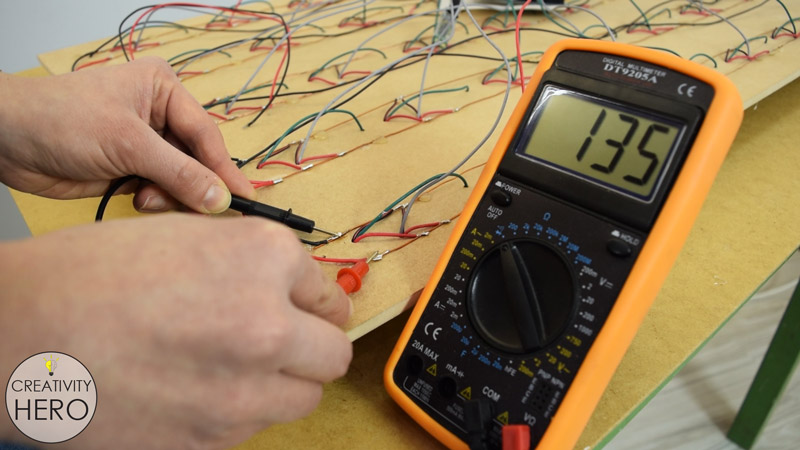
Before mounting the power supply I made a continuity test on the circuit, using a multimeter. The multimeter didn’t beep which meant my connections were all good.
Now I can mount the 5V power supply on the bottom of the table. It needs to be raised up just a little to get better airflow. Therefore, I glued two pieces of MDF, and placed the power supply above them.
Then I pulled the switch in and the main power cord into the appropriate holes and connected them to the power supply. 4 meters of the cord is enough for my space, so I cut it to size and wired a plug on its end.
After that I brought the MDF panel and connected the last two wires into the power supply.
Related: How To Build A Wooden Desk Lamp | DIY Project
Step 14: Programming the Arduino.
At this point we are ready to program the Arduino.
The code is fairly simple, it just reads the proximity sensors, and if an object is detected it lights up the particular LED.
For the color and brightness control we use the custom-built Android application. The data coming from the Smartphone is received via the Arduino Bluetooth module. As I mentioned earlier you can find detailed explanation on how this code works on Dejan’s article.
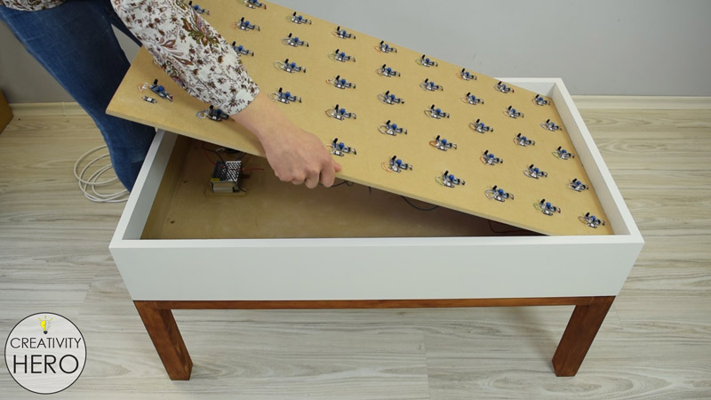
Once I uploaded the code, I placed the panel inside the LED coffee table.
Step 15: Making some Adjustments.
I noticed that the power indication LED of the proximity sensors would interfere with the main LED light, so I covered them with an electrical tape.
Making the grid is very easy. I just need to lock all the parts together, and as you can see they fit snugly.
Finally, I can put the matte glass on the top of the table, turn the switch on and check if everything works properly.
One of the LEDs doesn’t turn on when I placed a glass on top of it, so I removed the glass and adjusted the transmitter. It needs to be positioned at the right angle to be able to reflect the light to the receiver.
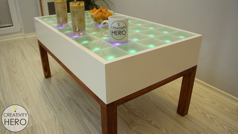
Now I can say that I’m finally done with this project!
This interactive LED coffee table turned out perfect. I like every part of it, including the design, the color change, and the brightness adjustment. It gives another dimension to my living room.

I hope you enjoyed this amazing DIY project. If you like this LED coffee table give me a thumbs up, leave a comment below, and subscribe to my YouTube channel.

hello marija my name is alonso I’m from Mexico I love your videos especially the DIY Interactive LED Coffee Table you know is something very father is an expression that we use in Mexico when something we like a lot, finally the electrical part is complicated by that I am very bad with that you could put a diagram or photo of how the cables are connected entresi by colors by ejenplo I would like it a lot thank you I hope to continue uploading videos greetings
Hi Alonso! I’m glad you like my videos. You can find a circuit schematics below in this article, it can help you understand how everything is connected.
awsome job i like it
Thank you so much!
Great idea!
Well explained project.
LOVE IT
Thank you so much! 😀
Great job! I love it.
Just a question. What kind of glass is used to cover the squares?
Regards.
Thank you so much! I used 4 mm thick frosted glass.
Great, Great job. hat’s off and such efforts. Thank you for sharing. Hope lot more DIY will come.
Thank you very much! 😀
Great job! I love it
Just a question how can found the app??
Hi Hamdi! Thank you so much! You can find the app on Dejan’s website HowToMechatronics. The link to the website can be found in this article.
Hi. Could you explain my one issue? I will be very grateful. I am wondering how it works and to be honest i have a problem with understanding it. Probably the answer is obvious. So… We have two obstacle. The glass top and for example cup or our hand which is put on top. And here is a problem. How sensor interpret it? And why when it detects two obstacle the state is LOW not HIGH?
Hi Paul! Well the IR Proximity sensor works in that way, when an obstacle is detected it outputs LOW instead of HIGH. The glass in this case is not an obstacle because the IR transmitter and receiver are adjusted so that the IR light travels through the glass. So, if an object is detected above the glass the IR light will bounce back through the glass and it will be received at the IR receiver.
Thanks Marija! Greetings 🙂
You’re welcome! 😀
Hello Marija,
Great table. I was in the process of dreaming a very similar piece of furniture when I found your article. Are you able to tell me how much power the whole thing draws and/or how many amps your power supply is rated for?
Hi Nick! Well each LED consumes up to 60 mA when the color is white at full brightness, so that would be 45 x 60 = 2.7A only for the LEDs. In addition, each IR Proximity sensor consumes around 40mA when active and plus we have the Arduino Mega board. So I would go for power supply with at least 3A. In my case I used 6A power supply.
Wow! I love it. I am wondering though how much does it cost to get all the components of the table?
Thanks! The total cost of the table was around 100$, which I think is quite cheap.